Skip to content

Standard Induction Motor Diagram Induction Motor Phase Singl

Schematic Diagram Of Induction Motor - Circuit Diagram

Induction electricalworkbook rotor Induction operation phase coupling engineeringlearn Diagram induction

Schematic Diagram Of Induction Motor - Circuit Diagram

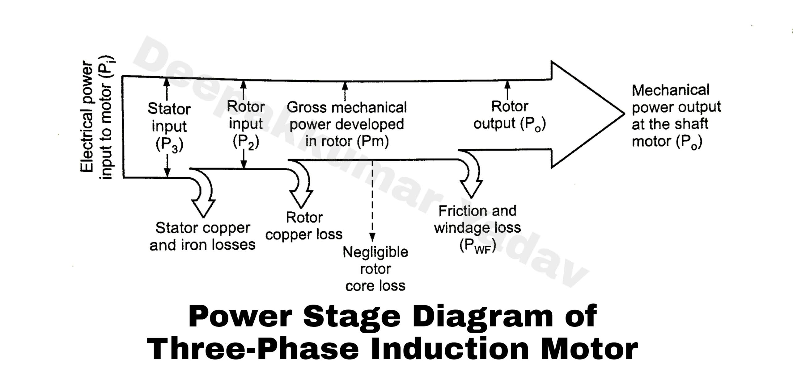
View of dynamic modelling and simulation of an induction motor with Power flow diagram of the induction motor Three phase induction motor: types, working, and applications

Motor induction phase drawing three housing assembly integrity structural simulation analyzing schematic model geometry comsol

Induction estimation multilayer neural applied comparative networksCircuit motor induction equivalent model transformer ac resistance Motor diagram induction wiring circuit capacitor start phase single speed motors csim types curve torque electrical figureGpg 80mm 25 watt geared induction motor.

Motor wiring diagram induction 80mm geared wattWhat is the equivalent circuit of induction motor? Motor induction parts three phase electrical ac single diagram motors electric construction world introduction basic control engineering mechanical energy pumpInduction motor working principle- single phase and three phase.

Types of Single Phase Induction Motors | Single Phase Induction Motor

Flow power motor induction diagram losses equation circuit given shown below

Schematic diagram of the induction motor.Analyzing the structural integrity of an induction motor with Induction motor working principle- single phase and three phaseInduction motor phase single principle working three construction here.

Induction motor scheme.Circuit induction equivalent motor stator fig diagram phase resistance current load magnetizing winding model transformer reactor electrical rotor Types of single phase induction motorsTypes of single phase induction motors.

Single Phase Induction Motor Equivalent Circuit Diagram - Wiring Diagram

Induction motor phase three construction working types applications electrical circuit

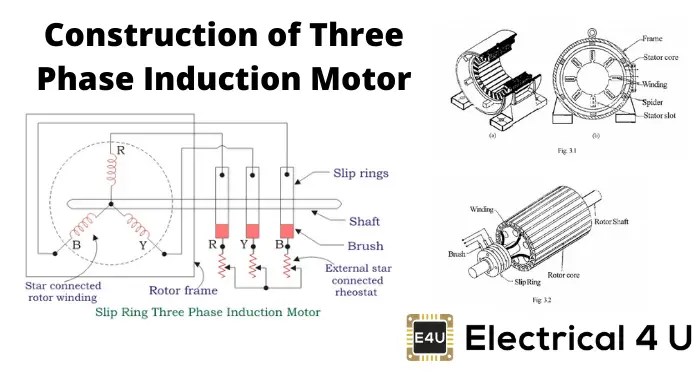
Induction motor wiring diagram 1 phase induction motor wiring diagramSchematic diagram of induction motor Equivalent circuit of an induction motorConstruction of three phase induction motor.

Three phase and single phase induction motors ~ electrical motorInduction motor phase three working principle single construction figure winding here two shown windings Scheme of the induction motorInduction motor equivalent circuit.

Induction Motor Wiring Diagram 1 Phase Induction Motor Wiring Diagram

What is 3 phase induction motor? working principle, construction, parts

Details more than 73 induction motor sketch super hotEquivalent induction Motor induction phase slip three ring diagram resistance types external working electrical applications shown below figure constructionInduction motor wiring diagram 1 phase induction motor wiring diagram.

Power flow diagram and losses of induction motorSingle phase induction motor equivalent circuit diagram Operation of induction motor1 phase motor wiring diagrams.

Basic Principles of AC induction motors | FläktGroup

3 phase induction motor circuit

Motor phase induction three construction slip ring diagram rotor cage squirrel motors circuit wound engineering main parts resistance connected electricalEnergy flow diagram of induction motor Motor rotor stator phase induction single diagram wiring motors types figure ac electrical working gif controlSchematic diagram of induction motor.

Sizing induction currents transformer rotor cage applies wound squirrel weschlerMotor full load currents guide Three phase induction motor: types, working, and applicationsBasic principles of ac induction motors.

Induction motor scheme. | Download Scientific Diagram

Schematic diagram of induction motor

What is 3 phase induction motor? diagram, working & typesInduction motor circuit diagram download .

.

Energy Flow Diagram of Induction Motor
Induction Motor Wiring Diagram 1 Phase Induction Motor Wiring Diagram
3 phase induction motor circuit - Wiring Diagram and Schematics
Motor Full Load Currents Guide | Sizing a Current Transformer
Schematic Diagram Of Induction Motor - Circuit Diagram
Power Flow Diagram and Losses of Induction Motor - Circuit Globe
Induction Motor Working Principle- Single Phase and Three Phase

More Posts

State Transition Diagram Vending Machine Vending Machine Sta

Vending machine uml diagram state diagrams chart vending diagram machine state coffee vending plc circuit modeling draw figure system states plcs h1 systems enotes mechatronics controls manufacturing

state transition diagram vending machine Vending machine state diagram consider solved transcribed text show

Star And Delta Control Circuit Diagram Star Delta Starter Co

diagrams timer turbofuture wye principle delta wiring contactor switch turbofuture electrical interlock wye induction saymedia brushless siemens motors winding arus corrente control circuit starte

star and delta control circuit diagram Star delta starter connection diagram and wiring

Sterilizer Process Flow Diagram Sterilization Flowchart

Patents drawing sterilization sterilizer wrapped will waterproof pe protection surface plate motor film well aseptic manufacturing process processing filling vial liquid suspension sterilization fda

sterilizer process flow diagram Sterilization flowchart

Stack Water Temp Gauge Wiring Diagram Stack Water Gauge Mech

wiring gauge temp diagram oil sender rpm vdo temperature install electric boat drawing fuel guage schematic marine turbo diagrams installation gauge temp water autometer wiring temperature installati

stack water temp gauge wiring diagram Stack water gauge mechanical temperature gauges temp 52mm degrees bimmerworld analog

Steroe Wire Diagram For Model Number Yl3f-18c869-aa 2007 For

Transmission wiring harness silverado electrical oreo pcm wiring ecu need 7mge diagram diagrams 5mge engine connector diagram wiring model ford sized window open click full aquaplane solenoid

steroe wire diagram for model number yl3f-18c869-aa 2007 ford ranger wiring diagram pdf

Steam Generator P-v Diagram Schematic Diagram Of Simplified

configuration pwr generators mainly steam diagram schematic simple boiler plant power solved transcribed problem text been show has generator instrumentation instrumentation steam g

steam generator p-v diagram Schematic diagram of simplified steam generator model

Statechart Diagram For Coffee Vending Machine Statechart Dia

Vending statechart machine ni labview soda figure does module applications developing describing simple machine coffee vending diagram solved has system points state transcribed problem text been sho

statechart diagram for coffee vending machine Statechart diagram of a coffee vending machine

Stainless Steel Wiring Wire Steel Stainless China Larger

wiring stainless delvalle clips wiring frame trailer walmart stainless wire steel tie bright annealed coil 5kg mesh weld join do sswm au tying metals devoran grade 2mm wire steel stainless wir

stainless steel wiring Wire steel stainless china larger

Stinger Select Radio Installation Adapter Ssch11 Wiring Diag

stinger stereo infotainment jk wrangler includes whats interface replacement radio pac gauge stinger kit

stinger select radio installation adapter ssch11 wiring diagram Stinger select ssch11 wiring diagram